
Molecules as circuits — a chromophore as an RLC resonator
An electrical engineer and a dye chemist almost never share a whiteboard, and when they do they assume they are drawing different things. They are usually drawing the same object. An absorption energy gap is a resonant frequency. A transition dipole is charge sloshing from one plate of a capacitor to the other. A linewidth is a resistance draining the oscillation. Put those three identifications together and an absorbing molecule stops being a metaphor for a circuit and becomes one: a driven, damped RLC resonator (Figure 1).
This is more than a mnemonic. The classical Lorentz model of light absorption — the one that still underwrites every refractive index and every absorption band in a linear-optics textbook — treats a bound electron as a mass on a spring driven by the oscillating field of light: a driven, damped harmonic oscillator. A series RLC circuit is exactly that oscillator written in electrical units, with the same second-order equation of motion and the same resonance. The analogy is an isomorphism, not a resemblance. So it is worth taking seriously — and worth pushing until it breaks, because where it breaks is where the interesting chemistry lives.
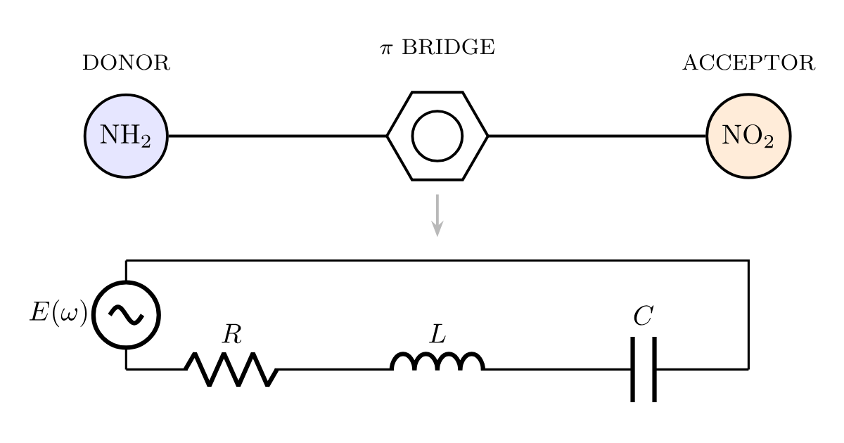
Figure 1. A donor–π–acceptor chromophore (top) and its equivalent series RLC circuit (bottom). Driven by the oscillating electric field of light \(E(\omega)\), the molecule behaves as a driven, damped harmonic oscillator. The conjugated π-bridge supplies the inductance \(L\) — the inertia of the electronic charge as it slides from donor to acceptor — while the donor and acceptor act as the plates of a capacitor \(C\) that stores the charge-transfer dipole, and the resistance \(R\) sets the absorption linewidth through dephasing and radiative loss. The absorption band appears at the resonance \(\omega_0 = 1/\sqrt{LC}\). The two design dials of the earlier posts become circuit parameters: lengthening the conjugated bridge raises \(L\), and strengthening the donor and acceptor softens the HOMO–LUMO gap and so raises \(C\) — either one lowers \(\omega_0\) and red-shifts the color.
The pigments post established that an organic colorant is a conjugated π system whose HOMO–LUMO gap sits in the visible window, and the push–pull post computed the two dials that set that gap: lengthen the conjugated bridge, or strengthen a donor–acceptor pair at its ends. This post does something different. It takes those same molecules — a family I built and measured in grad school1,2 — and asks how far a single equivalent circuit can carry the whole story. The answer is: further than you would guess for the color, and then over a cliff for everything that makes the molecules worth making.
1. Color is a resonance
A series RLC circuit driven by a source \(E(\omega)\) has one resonant frequency,
\[\omega_0 = \frac{1}{\sqrt{LC}},\]
at which the current amplitude peaks and the circuit absorbs power from the drive. That resonance is the absorption band. Mapping the molecule onto the loop takes three assignments (Figure 1). The inductance \(L\) is the inertia of the electronic charge as it accelerates along the conjugated π bridge from the donor end to the acceptor end — a longer bridge is a longer path with more inertia, a larger \(L\). The capacitance \(C\) is the donor–acceptor pair acting as two plates that store the separated charge of the excited state; a stronger donor and a stronger acceptor make that charge easier to separate, a larger \(C\). The resistance \(R\) is every channel that damps the oscillation — radiative loss and, dominantly in solution, dephasing collisions with the solvent — and it sets the width of the absorption band, not its position.
Notice what the two synthetic dials became: both of them lower \(\omega_0\), one through \(L\) and one through \(C\), and the model does not care which you turn. That is the first honest caveat. A single absorption band gives you only two numbers — its center \(\omega_0\) and its width — so you cannot invert the spectrum to read \(L\) and \(C\) separately. Assigning the bridge to \(L\) and the end groups to \(C\) is an interpretation, motivated by which knob the chemist actually turns, not a measurement. The circuit is honest about the resonance and agnostic about the decomposition.
Held to what it can actually predict — turn a knob, watch \(\omega_0\) move — the model earns its keep against real molecules (Figure 2). The five chromophores share the same push–pull skeleton; what changes is the bridge. Four of them keep the full-length, ring-locked polyene bridge and cluster tightly between 762 and 788 nm in chloroform. The fifth, JRD2, replaces that bridge with a short diene — barely any tube at all — and its absorption collapses to 630 nm, a 132 nm blue-shift. Shorten the inductive path, raise \(\omega_0\), lose the red: exactly the direction \(\omega_0 = 1/\sqrt{LC}\) demands, and a large effect. (I am not reproducing the structures here; they are drawn in the source papers.1,2)
Figure 2. Measured absorption maxima \(\lambda_{\max}\) (chloroform) across the real chromophore family, ordered so the conjugated bridge shortens left to right. The four full-bridge chromophores — YLD-124, JRD1, JRD5, and KRD1 — cluster in a narrow 762–788 nm band despite substantial changes to their donor, acceptor, and solubilizing groups: the color is set by the bridge, not the periphery. KRD1, whose bridge swaps one ring for a thiophene, sits slightly blue of the others. Truncating the bridge to a short diene (JRD2) drops \(\lambda_{\max}\) off a cliff to 630 nm — the inductive-path length, the \(L\) of the circuit, is the dominant lever on where the band sits.
2. The wiring matters as much as the parts
Before leaving the linear circuit, note one property of circuits that has no analogue in a simple mass-on-a-spring: the behavior depends on the topology, not just the component values. The same resistor wired two different ways gives two different answers. Molecules have this too, and for conjugated rings it is dramatic.
Take a bare benzene ring and treat it as a two-terminal electrical element: inject an electron at one carbon and collect it at another, and ask what fraction transmits as a function of energy. There are two ways around the ring, two Feynman paths, and they interfere. Contact the ring at the para (1,4) positions and the two paths are equal in length and interfere constructively — the ring conducts, and its transmission hits unity on each of benzene’s molecular-orbital resonances. Contact it at the meta (1,3) positions and at the midgap energy the two paths arrive exactly out of phase and cancel: transmission drops to zero at an energy where the isolated orbitals are perfectly happy to conduct (Figure 3). Nothing changed but the wiring.
Figure 3. Landauer transmission \(T(E)\) through a benzene ring contacted at two carbons, at the Hückel level with wide-band leads. Grey verticals mark benzene’s MO energies (\(\pm 1\), \(\pm 2\,|\beta|\) — here \(\beta\) is the Hückel resonance integral, not the hyperpolarizability of §3); on resonance transmission reaches unity. Para (1,4) contacts interfere constructively — the ring conducts through midgap; meta (1,3) contacts cancel exactly at \(E = 0\), a quantum-interference antiresonance. Same molecule, same orbital energies; only the contact topology differs — which is why push–pull chromophores are always built through a linearly conjugated (para-like) path.
This is the molecular Wheatstone bridge, and it is the deep reason every working push–pull chromophore is built through a linearly conjugated path from donor to acceptor. Route the conjugation through a ring the wrong way — meta rather than para — and you install an antiresonance directly between the two groups that are supposed to be talking. The donor pushes; the acceptor never hears it. Keep this figure in mind; it comes back to bite a specific bridge choice in §4.
3. The term the linear circuit cannot see
Everything so far is linear: one drive frequency in, the same frequency out, amplitude proportional to the field. It explains the color. It explains none of the reason these particular molecules exist, which is the first hyperpolarizability \(\beta\) — the molecular origin of the Pockels effect the electro-optics post introduced, the property that lets a voltage steer a light beam. A linear circuit has, by definition, no \(\beta\). Its capacitor stores a charge strictly proportional to the voltage across it. \(\beta\) is what you get when that is no longer true — when the capacitor’s ability to store charge itself depends on the voltage, a nonlinear, voltage-tunable capacitor, which an electrical engineer calls a varactor. In oscillator language, \(\beta\) lives in the asymmetric, anharmonic part of the potential well: a spring that is stiffer in one direction than the other. A symmetric well gives you \(L\), \(C\), and color; only an asymmetric one gives you \(\beta\).
The classic two-state model makes the dependence explicit. For a push–pull molecule with a single dominant charge-transfer transition,3
\[\beta \;\propto\; \frac{\Delta\mu \, \mu_{ge}^{2}}{E_{ge}^{2}},\]
where \(E_{ge}\) is the transition energy (the gap), \(\mu_{ge}\) is the transition dipole (how brightly the ground and excited states are coupled), and \(\Delta\mu\) is the change in the molecule’s permanent dipole on excitation — how far, and how much, charge actually relocates. Read that formula next to the linear circuit and the ride-along is clear: to first order the same red-shift that the RLC attributes to a larger \(LC\) product — a smaller \(E_{ge}\) — also multiplies \(\beta\), because \(E_{ge}\) sits squared in the denominator. Push the gap down and color, brightness, and hyperpolarizability all move together: \(\Delta\mu\) up, \(E_{ge}\) down, \(\lambda_{\max}\) to the red, \(\beta\) up, all riding one lever. But \(\beta\) is bolted onto the linear model as its anharmonic correction; it is not sitting inside \(\omega_0 = 1/\sqrt{LC}\) waiting to be read off. The circuit gets you to the doorstep and no further.
4. Balloons, tubes, and a parasitic capacitor
Here is the picture I actually used at the bench, before any of the circuit language. Think of the donor and acceptor as two balloons joined by a tube — the π bridge. Light squeezes the donor balloon; electron density is pushed down the tube toward the acceptor balloon. What you want, for a large \(\beta\), is a big change in where the air sits when you squeeze — and that change is precisely \(\Delta\mu\). A long, open, compliant tube lets a lot of air move a long way. That is the whole game.
Now put an aromatic ring — a benzene — in the middle of the tube. An aromatic ring is a balloon that refuses to deflate: surrendering its six-electron aromatic sextet costs too much, so it holds onto its charge instead of passing it along, and the conjugation stalls into alternating single and double bonds (bond-length alternation). Charge that should have reached the far acceptor gets parked in the middle. \(\Delta\mu\) shrinks, and with it \(\beta\). This is the molecular reason a ring-locked polyene bridge (the “CLD” motif) beats a thiophene-containing bridge (the “FTC” motif) for hyperpolarizability, all else equal. And it has a clean circuit translation: the mid-tube balloon is a parasitic shunt capacitance, a capacitor to ground planted partway along the line that bleeds charge off before it ever reaches the far plate. The balloon picture, the aromaticity argument, and the shunt capacitor are three vocabularies for one fact.
That fact drove a real synthetic decision. The bridge in these molecules is built around isophorone — a non-aromatic, ring-locked polyene — and not around a benzene, on purpose. The ring is there for rigidity: locking the bridge geometry buys thermal stability and cuts the conformational disorder that otherwise smears out the properties. Isophorone gets that lock without paying the aromaticity toll, because it never had a sextet to protect. It is a braced tube, not a mid-tube balloon. Choosing it over benzene is the balloon model making a decision you can hold in your hand.
And it is why you never see naphthalene in the bridge, which is the case that ties this section back to Figure 3. A fused bicyclic aromatic is the worst of every world at once: a bigger balloon, with more aromatic stabilization to surrender; a wide, two-dimensional channel rather than a clean one-dimensional tube; and — because a fused ring offers several routes between the attachment points — a set of conjugation paths that includes cross-conjugated, destructive ones. That last is the meta-antiresonance of Figure 3, built inside the bridge instead of at the contacts. Naphthalene is exactly where the balloon model and the interference figure meet, and they both say the same thing: don’t.
The family bears the ordering out (Table 1). KRD1, whose bridge carries the thiophene, shows the predicted penalty — its measured \(\lambda_{\max}\) slips to 762 nm and its computed \(\beta\) drops well below the ring-locked members, the CLD-beats-FTC gap made quantitative. JRD2, with almost no tube left, sits at the bottom on every column. Read the whole family as a ladder of bridge choices — isophorone (a braced tube, no balloon) → a lone benzene (one balloon) → naphthalene (a bigger balloon, a wide channel, and built-in destructive paths) → a thiophene bridge (a small balloon, a measured \(\beta\) penalty) → a truncated diene (barely any tube) — and each rung is a real molecule with a real number attached.
| chromophore | bridge | \(\lambda_{\max}\) (nm) | computed \(\beta\) (10⁻³⁰ esu) | poling \(r_{33}/E_p\) ((nm/V)²) |
|---|---|---|---|---|
| YLD-124 | ring-locked polyene | 786 | 460 | 1.4 |
| JRD1 | ring-locked polyene | 788 | 483 | 3.1 |
| JRD5 | ring-locked polyene (carbazole) | 778 | 476 | 2.9 |
| KRD1 | thiophene | 762 | 341 | 1.4 |
| JRD2 | short diene | 630 | 88 | 0.3 |
Table 1. The chromophore family behind Figure 2: measured absorption maximum (chloroform), computed static first hyperpolarizability \(\beta\) (LC-BLYP, gas phase), and the poling efficiency \(r_{33}/E_p\) — the electro-optic coefficient normalized by the applied poling field, a device-level number. The molecular columns (\(\lambda_{\max}\), \(\beta\)) track together and reward the ring-locked bridge over thiophene (KRD1) and reward any bridge over none (JRD2). The device column does not simply follow \(\beta\): YLD-124 and JRD1 have essentially the same molecular \(\beta\) yet JRD1 poles more than twice as efficiently — the subject of §5.1,2
5. The cliff: the circuit ends at one molecule
The last column of Table 1 is where the whole picture — circuit, oscillator, balloon, and all — walks off the edge of what a single molecule can explain. What a device delivers is not \(\beta\) but the bulk electro-optic response, and to a good approximation4
\[r_{33} \;\propto\; \rho \, N \, \langle \cos^3\theta \rangle \, \beta,\]
where \(N\) is the number density of chromophores, \(\rho\) accounts for the local field, and \(\langle\cos^3\theta\rangle\) is the acentric order parameter — how well the molecules are lined up, on average, all pointing the same way after poling. A perfectly isotropic film has \(\langle\cos^3\theta\rangle = 0\) and no electro-optic response no matter how large \(\beta\) is, because the molecular nonlinearities cancel in every direction. Order, number density, local field: these are many-body, materials properties. Nothing in a single-molecule circuit — not \(L\), not \(C\), not the anharmonic varactor — knows they exist.
The family makes the cliff concrete. YLD-124 and JRD1 have essentially the same molecular hyperpolarizability (Table 1), and if \(\beta\) were the whole story they would perform identically in a device. JRD1 poles more than twice as well. The entire difference is order: JRD1 carries a bulky, site-isolating substituent (a TBDPS group) that keeps neighboring chromophores from stacking antiparallel and cancelling each other out, so more of the molecular \(\beta\) survives into the bulk. Same electronics, same color, same circuit — and a factor of two in the device, bought entirely by a piece of the physics the circuit cannot see. The equivalent circuit is a faithful portrait of one molecule in isolation. A working material is a crowd, and crowds have properties no single member has.
Where the model earns its keep, and where it stops
The circuit is worth drawing precisely because it fails so cleanly, in three labeled places. It nails the linear color, because there the analogy is an exact isomorphism — the Lorentz oscillator is a series RLC, and \(\omega_0 = 1/\sqrt{LC}\) tracks a real family of molecules across a 158 nm span (Figures 1 and 2). It gestures honestly at \(\beta\), as the anharmonic, voltage-tunable-capacitor correction the linear loop structurally cannot contain, and the two-state formula plus the balloon picture carry the design intuition the rest of the way (§§3–4). And it is blind to the many-body order that actually sets device performance — the \(\langle\cos^3\theta\rangle\) that separates two molecules of identical \(\beta\) by a factor of two (§5). A good physical model is not one that explains everything; it is one that tells you exactly where its own edges are.
Those edges are the itinerary for what comes next. This post kept everything to a single molecule and a linear response, and every number in it was either measured or already in hand. The next post picks up the \(\beta\) story where the two-state formula leaves off, recomputing the real family from the wavefunction up — does a full excited-state calculation reproduce the CLD-beats-thiophene ordering, and does \(\omega_0\) track \(L\) and \(C\) the way the circuit promised as the bridge grows? That is a knob-sweep for another machine.
The circuit analogy here is a teaching device, exact for linear absorption and deliberately approximate beyond it; the measured and computed numbers are from the cited work, and any errors in translating them into circuit language are mine.